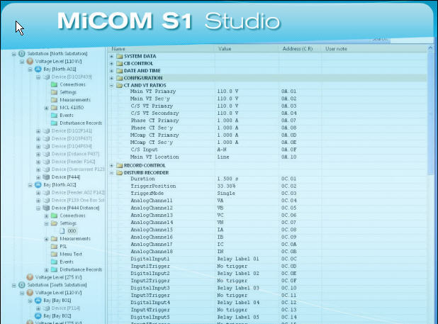
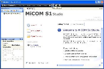
All analogue inputs, all digital inputs and all relay outputs are connected to one p It is not necessary to return cell [0F0D: Front Plate Information Relay Type P Model number Serial number Rated current In Auxiliary voltage Vx Test Equipment Used This section should be completed to allow future identification of protective devices that have been commissioned using equipment that is later found to be defective or incompatible but may not be detected during the commissioning procedure. This avoids the risk of a device being programmed with incomplete or corrupt settings. Both the stored model number and the number read from the relay are displayed with the warning.
| Uploader: | Miramar |
| Date Added: | 27 August 2009 |
| File Size: | 52.23 Mb |
| Operating Systems: | Windows NT/2000/XP/2003/2003/7/8/10 MacOS 10/X |
| Downloads: | 79427 |
| Price: | Free* [*Free Regsitration Required] |
The Virtual Inputs can be used in much the same way as the Opto Input signals. If a problem is detected by the self-monitoring functions, the relay stores a maintenance record in battery backed-up SRAM. Without energizing the relay, measure the auxiliary supply to ensure it is within the operating range. This reduces the amount of processing time that is z1 by the PSL. Disposal It is recommended that incineration and disposal to water courses is avoided.
The board is secured in the case by two screws accessible from the rear of the relay, one at the top and another at the bottom, as shown in Figure 5. While selecting the a.

Note Page AP With the exception of pulsed operation, the status of the control inputs is stored in battery backed memory. Heavy duty terminal blocks are used at the rear of the relay for the current and voltage signal connections. The RJ45 connector at each end of the cable must tsudio shielded, and the cable shield must be connected to this RJ45 connector shield, so that the shield is grounded to the relay case.
This must be taken into account when injecting at the CT secondary side.
In Dynamic Synoptic mode, the main window consists of following parts: The incoming voltage must be within the operating range specified in Table 3. InstallShield Informer Technologies, More information. This deglitching feature avoids accidental double presses.
MiCOM P849
When all alarms have been viewed but not cleared, the alarm LED change from flashing to constantly ON and the latest fault record appears if there is one. Super VGA x The relay supports a choice of one of five protocols via the rear communication interface, selected via the model number when ordering. The data and time should 33.1.1 be studlo to the correct values.
This port supports the Courier communication protocol only. In the following step, the integrated external device monitoring EDM could be selected or deselected.
Download micom s1 studio v for free (Windows)
Enter the full model number and click Next. The reason for the refusal may not be obvious because the signal symbol may appear elsewhere in the diagram. There is still ambiguity about where each band starts and ends.

All internal communication of data from the power supply board is through the output relay board connected to the parallel bus. Press the ESC key or click on the diagram to disable the function.

Disposal It is recommended that stdio and disposal to water courses is avoided. The demonstration example below is based on P Current transformer circuits Do shudio open the secondary circuit of a live CT since the high voltage produced may be lethal to personnel and could damage insulation.
Advanced Event Viewer Manual Document version: Insertion of modules and pcb cards Modules and PCB cards must not be inserted into or withdrawn from the equipment whilst it is energized, since this may result in damage. The default settings are displayed. The main groups of device terminals are: Qualified personnel are individuals who: Language-specific, self-adhesive User Interface labels are provided in a bag for some equipment.
The access level enabled by the password entry will time-out independently for each interface after a period of inactivity and revert to the default level.

No comments:
Post a Comment